u/pixilstix

Image 1 —
Image 2 —
Image 3 —

I'm doing a new picoboot mod on a GameCube today. I have done one that was successful already. This one is giving me more trouble than the other though. I have reflowed all of my solder joints at least one additional time, for some of the joints it was more than one. I think they all look good.

The symptoms are that the GC powers on but never outputs any video. If I plug the pico into the computer it is still working fine and I can upload the UF2 to it without issues. When I power the GC on the pico lights up green, but nothing ever shows on the screen. If I de-solder the power to the pico, the GC boots fine to the GC menu, so while I would love the solder connections on the chip on the board to look a little cleaner I am very sure there is no bridging going on.

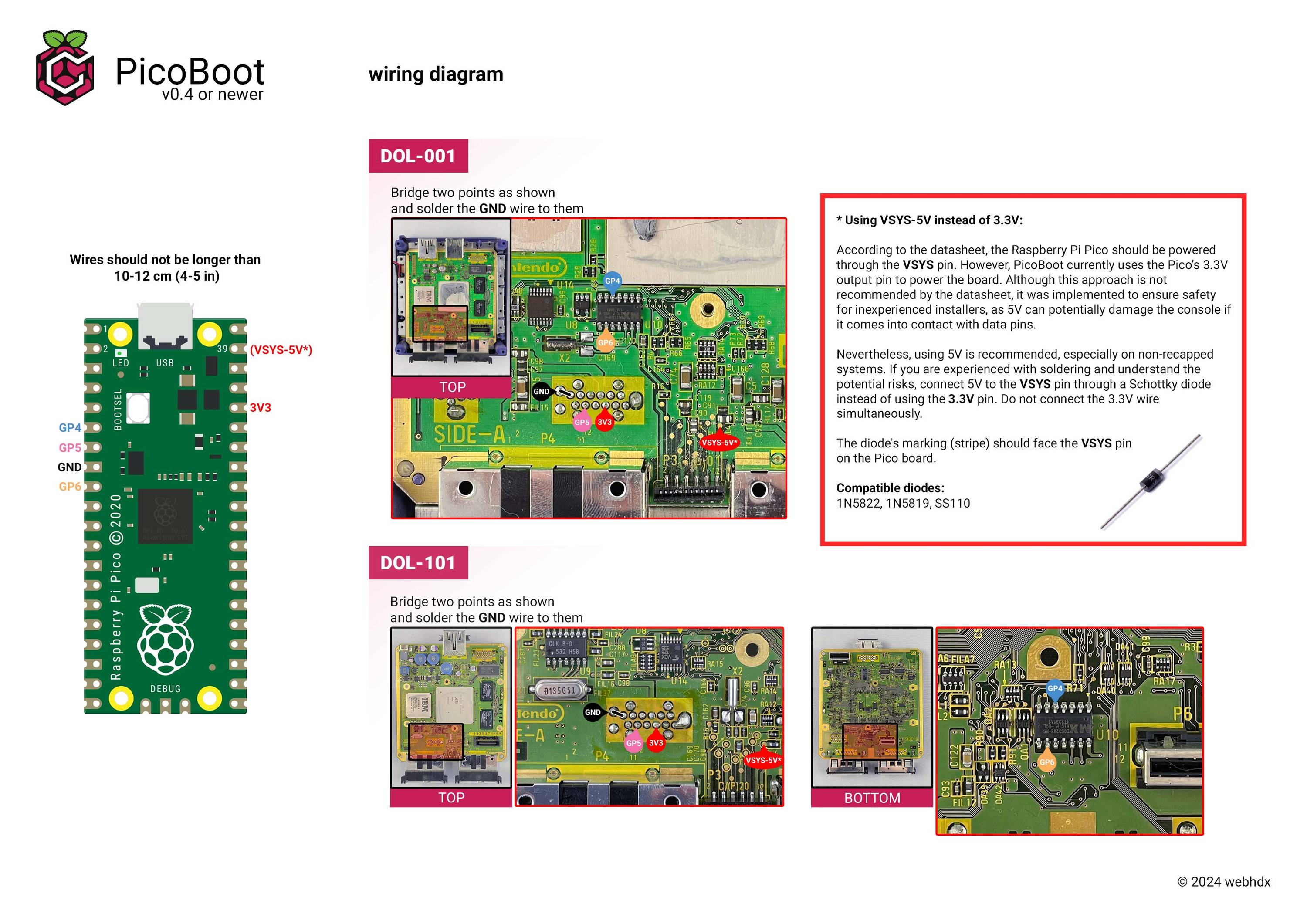
My wires are possibly a little long (4 - 4.5 inches?), but I believe the no video output is not a symptom of long wiring. Is that correct?

Thanks everyone! @Shartyshartfast correctly pointed out that two of my wires were in the wrong spot. I swapped them around and now they work perfectly.

u/pixilstix — 11 days ago

I have finished soldering up a second Gamecube to a Pi Pico board using the instructions on Web HDX's page for installing a Picoboot mod but neither of them have worked and they both have the exact same behavior. When I turn the GameCube on it just boots to the normal menu, no issues with the normal behavior of the GameCube, thankfully, but no trace of mod-like behavior. If I hold the d-pad down nothing happens either, which I'm told means the picoboard isn't soldered correctly OR the software wasn't installed correctly on the board.

I used flux for all my solder connections and used a magnifier so I could make sure none of the different solder points are bridging (except the ground line, which is supposed to bridge to the adjacent pin). The wires are all < 4" long, which is what Web HDX asks for.

I also watched the Nacho Productions YouTube tutorial to give me a bit more confidence in what I was doing. He claims in the video that after the mod is in place I can still hold BOOT SEL and plug it into a computer to update the firmware if I want, however, now that the solder job is done, it pops up in Windows for about a second and then disappears. The board also heats up really fast in my fingers while it's plugged in. Both of the GCs I have soldered this to are doing this. I haven't let it get hot for too long. On my first solder job I de-soldered all of the wires from the board except those that are under the heatsink and when I did that and then held BOOT SEL while connecting to a computer, it popped up just fine and allowed me to re-load the Picoboot software, but when I re-soldered everything it still didn't work and had the same heat up behavior as before.

Can someone help me understand what I must be doing wrong? I'm following this wiring diagram for DOL-001, which is the model of both GC's I've tried to mod. https://support.webhdx.dev/assets/ideal-img/wiring_diagram.4cb7874.3000.jpg. I didn't understand the part about the optional 5V wiring thing, so I just went with the vanilla wiring on the left, Nacho did the same thing in his YouTube video, so I was more comfortable doing it this way.

Appreciate the help!

UPDATE:

I have implemented several requests and suggestions for folks and have some new information.

  1. I de-soldered all connections from the GC main board, held BOOT SEL and plugged the Pico into my computer. It mounted just fine as normal and I re-uploaded the picoboot firmware. So this verifies the Pico is still working and that the firmware is once again loaded.
  2. I trimmed all wires by another 2 inches or so (depending on the wire) and re-soldered all connections to the GC main board. The new solder connections look better than the ones before.
  3. Just as before, when powering on my GC it goes straight to the main GC menu. No errors or problems, just no picoboot

I have new pictures that are hopefully better than yesterday's and that show the new GC soldering as well as under the heat sink this time. I didn't re-solder any connections to the Pico itself.

https://imgur.com/a/yuyZMFT

UPDATE 2:

Based on a lot of feedback from you guys I've decided to buy the diode to wire up the 5V instead of the 3V. I found someone showing how it's done and it looks pretty simple. I'll update here once I've made that change. It seems like a reasonable theory that it might not be getting the power it needs.

UPDATE 3:

The diodes came today, wiring up to the 5V rail was exceedingly simple and now everything works! Thanks all for the help. The LED now lights up on the Pico and it boots straight to the mod instead of the GC main menu.

UPDATE 4:

OK, I just realized I had the 5V rail on the GC MB connected to the 3V3 pin on the Pico still, so I moved it to the VSYS like the diagram calls for, but now it doesn't power again. Is there a reason using the 3V3 pin would be bad? It almost seems like this Pico wasn't built following the specs very well.

I've just ordered three new Pico boards from PiShop.us, they should be genuine ones this time and I'll probably return these bad ones to Amazon.

u/pixilstix — 20 days ago